CAD Takes Off

august14_AIRSHIPDESIGNCAD has revolutionized the concept of design. The downward trend of prices and the upward trend of performance of computers of all levels and the phenomenal growth of the CAD industry during the last few years portend a much wider implementation of CAD facilities in industries including aeronautical industry.

In the early years of aircraft design, for instance, designers generally used analytical theory to do various engineering calculations that go into the design process along with a lot of experimentation. In the 1940s, several engineers started looking for ways to automate and simplify the calculation process. They developed many relations and semi-empirical formula. Even after simplification, the calculations continued to be extensive.

With the invention of the computer, engineers realized that a majority of the calculations could be automated. However, the lack of design visualization and huge amount of experimentation involved kept the field of aircraft design away from the magical touch of computers for a long time – that is until computer aided drafting, or CAD was born.

The rise in computer technology was married with old design concepts to create CAD programs. These programs are used in a variety of fields but there is no industry in which it is more important than the aerospace industry. The high-tech aerospace industry manufactures everything from space vehicles to satellites, aircraft to missiles.

Uses of CAD in Aerospace

CAD software plays an integral role in the design process. But CAD is extensively used in various areas of aircraft engineering – from product development to manufacturing. It is also used to design and develop aerospace fixtures such as: Ground handling and ground support equipment, Assembly jigs & fixtures, composite structures, plastic Injection molding & forming die, and so on.

Before the product is built, every detail is thoroughly planned using the design software. CAD designed three-dimensional models help engineers, designers, and clients determine flaws and benefits of components in the project stage. An extensive three-dimensional model can help expose a dangerous or inefficient flight process.

CAD designers sit in on conceptual meetings and develop models of old planes to help determine areas where innovation is necessary. A CAD designer is often required with developing multiple computer models in order to play out ideas in the concept stage.

In addition to designing key components, CAD is used in process planning, concept definition, remote collaboration with customer, participation in assembly strategy, timely schedule challenges, process configuration, tooling, gage & fixture design and development, and manufacturing support.

What more, CAD also helps companies in documentation. The software can be used in preparing the documents like component maintenance manuals, illustrated part lists and illustrated part catalogues, aircraft maintenance manuals, engine maintenance manuals, troubleshooting manuals, wiring data manuals, structural repair manuals, illustrated tool and equipment manuals, service manuals, repair manuals, training manuals, and assembly animations.

CAD Software in Airship design

CAD software proves to be indispensable in designing airships for geo-survey, military surveillance, and weather monitoring. The software helps perfect ship designs before they are built.

Starting from the 3D geometry of the spacecraft or instrument the 3D model delivering, everything is designed with the help of CAD. Satellites are built using the graphical CAD tools to design and analyze the control systems; perform disturbance analyses and test the control system in a six degree-of-freedom simulation. With the commercially available multi-body dynamics software and its interface to the computer aided design (CAD) software, all the moving elements in the deploying process can be modeled.

NASA uses CAD to create 3D printed satellites – tiny wafers that could be deployed by the hundreds from a mother ship – to cheaply transmit research data back to the earth. CAD is used to ensure that parts are made to exact specifications. Those CAD-created designs could be transmitted to outer space. The goal of the effort is to commoditize parts for the aerospace industry, making them cheaper to create and send into orbit and beyond. Astronauts could use 3D printing to experiment by making their own objects or producing replacement parts for things that break.

NASA, as a whole, and Goddard Space Flight Center in particular, a pioneer in the field, has highlighted the work areas for concentration, and, having the most advanced CAD systems and facilities available, will continue to use and develop advanced software for special and general purpose use.

Another case in point is 21st Century Airships. It chose CAD to move away from a paper-based design environment so that they could fully automate their design processes to improve accuracy and increase efficiency. CAD has not only helped them improve efficiency, they have improved on profitability too. With CAD, 21st Century Airships are able to produce higher quality airships more quickly and cost-effectively. Since they have started using CAD they have developed approximately 18 unique airship designs. 21st Century Airships also chose CAD because it is the design standard throughout the aviation industry.

CAD Software in Aircraft Design

Airframes, the body of the aircraft, are extremely complex, and the growing use of composite structures makes them that much more difficult to engineer. Today’s “new world” airframe design calls for digital model-based definitions that minimize the tedious, time-consuming process of creating drawings, while taking into account new composite materials, manufacturing technologies and globally distributed partners

In aircraft design, CAD software is used to:

  • Employ a single interface for capturing and authoring design details
  • Define information concerning non-modeled parts such as coatings, sealants, labels and inserts
  • Define joint definitions and part relationships
  • Determine fastener specifications and locations to ensure accurate part manufacturing
  • Streamline the supply chain and share detailed data across supplier organizations
  • Develop the inputs for automated hole drilling and fastener installation systems

More than 25,000 aircraft will be produced in the next 20 years by companies like Boeing and Airbus. In general, CAD software has boosted efficiency of aircraft design by about 60%, and thus increased profitability of the companies, significantly.

Revit Architecture 2014: Instant Revisions Made Possible

july-14_cRevitarchiteRevit stands for revise instantly – representing a software system that automatically updates a change made in one view in all other views and schedules. a major goal of Revit software from Autodesk is to eliminate much of the repetitive and mundane tasks traditionally associated with cad programs allowing more time for design, coordination and visualization.

Revit utilizes a parametric model (3D based) to generate plans, sections, elevations, perspectives, details and schedules – all of the necessary instruments to document the design of a building. drawings created using Revit are not a collection of 2D lines and shapes that represent a building. instead, they are live views extracted from what is essentially a virtual building model.

The best way to understand how a parametric model works is to describe the Revit project file. a single Revit file contains your entire building project. even though you mostly draw in 2D views, you are actually drawing in 3D. in fact, the entire building project is a 3D model. from this 3D model you can generate 2d elevations, 2d sections and perspective views. Revit comes in three different flavors: Revit architecture, Revit structure and Revit MEP (which stands for mechanical, electrical, and plumbing).

Design: Revit is 4D BIM capable with tools to plan and track various stages in the building’s lifecycle, from concept to construction and later demolition. using Revit, you can design a building and structure and its components in 3D, annotate the model with 2d drafting elements and access building information from the building models database.

A building model in Revit consists of intelligent components that contain not only physical attributes but also functional behavior familiar in architectural design, engineering and construction. all design elements in Revit share a level of bidirectional associativity – that is, if elements are changed in one place within the model, those changes are visible in all the other views. for example, if you move a door in plan, that door is moved in all of the elevations, sections, perspectives, and so on in which it is visible.

Many architectural designs are too complex to be accomplished using a conventional method like designing it going by the floor plan. using Revit you can create building concepts before actually creating building elements. sketch freely and create free-form models.

Analysis: Energy analysis for Revit software is a cloud-based energy simulation service powered by green building studio that supports sustainable design. you can do the structural analysis of calculating the effects of loads on physical structures and their components with Revit effectively. the software comes with cloud-based structural analysis software that supports building structural analysis as part of the bim process. Revit software works the way architects and designers think, so you can develop higher-quality, more accurate architectural designs. view features to see how you can use architecture design tools built to support BIM workflows.

Documentation and reports: creating documentation using BIM gives you the added advantage of being able to visualize the project in 3d. you can create a seemingly unlimited number of interior and exterior visualizations. customers can virtually walk through the building at their own pace, exploring an endless variety of directions. you can use Revit also to instantaneously generate reports on component quantities and space usage, whereas plans, sections, and elevations afford you the flexibility to customize their display using the information embedded in the modeled elements.

Autodesk revit is widely used by architects, structural engineers, MEP engineers, designers and contractors.

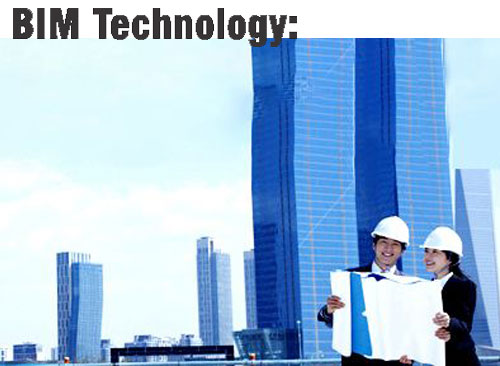
BIM Technology: Intelligently Linking Drawing and Database

july14_bimTwenty five years ago, nearly every drawing produced in the world was done with pencil or ink on paper. Minor changes meant erasing and redrawing while major changes often meant recreating the drawing from the scratch. If a change to one drawing affected other documents you were dependent upon having someone manually recognize the need to make the changes to the other drawings and to do so.

However, Computer Aided Design (CAD) has fundamentally changed the way design is done. Architectural practice continues to be increasingly influenced by and dependent on computer technology. The latest evolution of CAD in architecture is Building Information Modelling (BIM) technology that has disrupted traditional methods of representation and collaboration in architecture. BIM is one of the most promising developments in the architecture, engineering, and construction industries. With BIM technology, an accurate virtual model of a building is constructed digitally. When completed, the computer generated model contains precise geometry and relevant data needed to support the construction, fabrication, and procurement activities needed to realize the building.

BIM is born out of parametric design and relational database concepts. Ultimately, BIM leverages these two concepts to intelligently link drawing and data, and let the users see buildings through the lens of a database.

To get an idea of how BIM works, we should know what is parametric design and relational database.

Parametric Design Parametric design is a process used to manipulate, regenerate and design objects based on a set of rules or parameters.

Original CAD software used explicit, coordinate-based geometry to create architectural graphic entities such as a wall or hole. Editing these “dumb graphics” was cumbersome and extremely error prone. Then came parametric modeling software -they used parameters (numbers or characteristics) to determine the behavior of agraphical entity. For example, parameters can be defined such as: “the diameter of this hole is 1 inch” or “the center of this hole is midway between these edges.”

One way to understand BIM is that it enables users to tie their drawings with numbers or characteristics – or simply data or information. Is that all? No! BIM ties drawing with database – a relational database.

Relational Database:

A relational database is a method of structuring data as collections of tables that are logically associated to each other by shared attributes.

Databases have been a staple of business computing from the very beginning of digital era. You may know how to create a table with columns and rows in MS Excel or MS Word and store information in appropriate places in the table. How about creating a table that has a minimum of thousands of tables? And then let one table talk to another table or one column of a table talk to another column of a table!

Here is an analogy: you can compare tables to houses in a colony. Assume that each house is linked in some way and the kitchen of a house can talk to the kitchen of another house – that is make use of utensils and food materials of the kitchen of another house. Now you get the picture, right?

In relational database tables and their components are linked to those of others and information can be stored and retrieved among all the tables.

Benefits:

The BIM technology lets users to design architectural graphic entities using parameters and lets the information of these entities stores as data using organized tables. Every element in a BIM model comes with editable attributes that are stored as data in a table.

BIM allow architects, owners and other design professionals to have ready access to an ever-increasing body of information or data from which to make decisions.

BIM changes the way companies work – both internally and externally. Projects have become more and more complex, requiring firms to manage and share immense amounts of data across diverse and distributed teams. By enabling greater insight into the project at any point in its lifecycle, BIM helps AEC service providers to improve accuracy, efficiency, and productivity, resulting in time and cost savings.

The significant value-added benefits that BIM ready firms can provide include: faster project approvals, more predictable outcomes, sustainable design and analysis services, and improved collaboration and information sharing for integrated project delivery strategies.

The increased potential for collaboration that comes with BIM can have a great impact on your business models, the types of projects on which you bid, and the partners, clients, and consultants with whom you choose to work. The ability to digitally collaborate on a building’s physical and functional characteristics strengthens and deepens existing partnerships — and forges new ones between architects, engineers, contractors, and owners.

BIM allows us to work on much more complicated structural engineering projects than were attempted in the past. Architects are using more and more complicated geometries. BIM allows us to share the geometries back and forth among the design team members much more easily.

The ramifications of that new level of collaboration are felt across all the organizations involved in a project, reaching far beyond the design groups and affecting most aspects of each firm’s business.

BIM can also affect the way a company delivers its products, enabling AEC service providers to deliver more 3D views, sections, schedules, and realistic renderings in construction documents. BIM also improves the quality of the final product.

Conclusion

Implementing BIM will result in changes to your design process, drawing production, and project team organization. Perhaps the biggest process change that firms encounter has to do with the very act of designing. Design representations are no longer 2D drawings. Instead, designers are using 3D digita models that are assembled in the same way a building is constructed. The ability to look at all these aspects together in a holistic manner is of tremendous value.

The use of BIM tools is increasing the level of effort during early design and also speeds up your backend production processes. More importantly, results in a higher quality, more sustainable building with fewer requests for information and construction change orders.

SolidWorks 2014 – Factsheet of Features

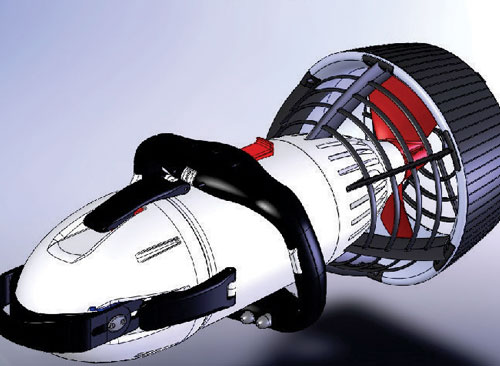
june_14_3dcadSolidworks is a Solid Modeling cad software that runs on Microsoft windows. Solidworks was developed as a 3d cad software that was easy-to-use, affordable, and available on the windows desktop. It is currently used by over 2 million engineers and designers at more than 165,000 companies worldwide.

The latest version of the software Solidworks 2014, covers all aspects of product development process with a seamless, integrated workflow – design, verification, sustainable design, communication and data management.

Designers and engineers can span multiple disciplines with ease, shortening the design cycle, increasing productivity and delivering innovative products to market faster.

3D CAD: Solidworks 3D CAD solutions enable you to quickly transform new ideas into great products. it comes with ECAD/MCAD collaboration, reverse engineering, and advanced wire and pipe routing functionality features

Simulation: you can subject your designs to real-world conditions to raise the quality of your products while you reduce your costs for live prototypes and testing including motion analysis, electronics cooling, fatigue analysis, structural optimization, thermal analysis, and structural analysis. There are also additional tools for simulating nonlinear and dynamic response, dynamic loading, and composite materials.

Product data management: Easily find and repurpose files, parts, and drawings; share design information; automate workflows and ensure manufacturing always has the right version. Solidworks product data management (PDM) solutions help you get your design data under control and substantially improve the way your teams manage and collaborate on product development. With Solidworks enterprise PDM enable your teams to: securely store and index design data for fast retrieval; eliminate concerns about version control and data loss; share and collaborate on designs with people inside and outside the organization in multiple locations, and create an electronic workflow to formalize, manage, and optimize development, document approval, and engineering change processes.

Technical communication: effectively communicate complex product details by leveraging existing 3D CAD data across your organization to create polished content and Animations.all project design data is synchronized in real time, Bi directionally between schematics and the 3d model within a collaborative environment.

Electrical design: combine the electrical schematic functionality of Solidworks Electrical Schematic with the 3D Modeling capabilities of Solidworks electrical 3D and do it all in one powerful, easy-to-use package. Solidworks Electrical Professional is ideally suited for the user that supports both the electrical and mechanical design integration.

Solidworks Mechanical Conceptual: for design professionals and teams who want to create and collaborate without constraints, Solidworks 3dexperience software, powered by Dassault Systèmes 3dexperience platform, provides a conceptual, instinctive, social, and connected development experience that gives you the freedom to design the way you want.

 The software comes in three different packages: Solidworks Standard, Solidworks Professional, Solidworks Premium, and Solidworks education edition. The premium version is the most comprehensive of all – it provides a suite of product development tools mechanical design, design verification, data management, and communication tools.

Broader Education is the new B.E

june14_solioCompetence of an industry comes from its expertise in one of the discrete domains in science, technology, engineering and mathematics (again, stem). Take the example of Google. it was built based on an innovative search algorithm (a mathematical domain). The name “Google” is a play on the word “Googol”, a mathematical term for a specific number of 1 followed by 100 zeros.

But “stem” is not enough for a “plant” to grow. an organization needs new “branches” of human intellect to become successful in the longer run – broadly, the new areas could be the art of usability, and sciences of sociology, and environment.

The key point of this article is that it is not enough for engineering students to know just engineering, but also other art forms to introduce innovative products to the world. the success of apple, and Steve jobs is a pointer.

One can attribute the market dominance of apple not just to engineering but to design. a tablet product was pioneered not by apple. There were many precursors to tablet. In fact, Wipro had a tablet like product called e.Go. but what made apple’s tablet very famous is its design focus.T the company looked tablet not as a hardware or software, but a design that would give an unique experience to customers.

Apple successfully married arts and science, in a way. it was not for the first time, Apple’s Mac OS was the first operating system to have come with a graphical user interface. The question is what helped apple infuse design and engineering. it was the “broader education” that apple’s founder and CEO, Steve jobs had. While still at college, Steve jobs learned a course on calligraphy. His ideas of good looking fonts, when applied to programming codes, became graphical user interface that we all enjoy using today.

Why is “broader education” important? in other words, why engineers are expected to be out of the box innovators, having at least rudimentary knowledge in subjects like sociology, environment, and usability? The reason is: to design successful products.

System thinking: engineering is all about creating products. Typically, engineers will start designing a product with the brief they get from the management. Design, in a way, is the process of making right trade-offs within the given context. Designers need clarity on the context to make the trade-offs. A luxury or affordable car market gives enough clarity for the designers. The job of the designer is to make suitable trade-offs among the three constants, depending on what market segment the product in question is being designed for. The design of an Audi does not have to bother too much about cost, while the design of a Nano cannot afford to work on comforts at the cost of affordability.

Traditionally, innovations aim to improve existing product ideas in terms of time, cost, and quality. The game is about making a product “faster, cheaper, and better”. But now engineers have to connect new dots to make a product successful.

Product failures: let us look at some of the case examples of product failures first.

Case Example 1 : Poor, rural hospitals in African and Asian countries had to discard sophisticated incubators, donated by aid agencies to save just born babies. The reason: the incubators are too high-tech to be repaired by local mechanics.

Case Example 2: The US government has reportedly demolished over 500 dams in the recent past. Because, the government has found that dams affect eco-systems and thus, the supply of ecosystem services, without which agriculture cannot flourish.

Case Example 3: In urban centres, growing car population causes traffic jams. car is a failure product in a specific city settings.

Product innovations such as incubators, dams, and cars once wowed the world but they have become undesirable in certain contexts of social, economic, demographic, or environmental settings.

Broader education is the way out. Because broader education helps engineers think about the larger systems. let us go back to the three cases of product failures and see what happens when we apply broader education.

“cost effective” incubator for “rural technical support” system: A multi-stakeholder group, facilitated by Stanford, created a low-cost incubator with automobile parts so that they can be repaired by an average two-wheeler or car mechanic, who are easy to find anywhere in a developing country.

“Better” dam for “eco-hydro-livelihood” system:With the understanding that water alone cannot produce results in an agricultural field, our innovators can set creating an “eco-friendly and livelihood friendly” water storage and supply system, as their context.

“Smarter” car for “inter-modal-transport” system: one solution proposed to avoid the global gridlock, as enumerated by Mr Bill ford of ford motor company, is to design smart internet of transport things: smart cars, smart roads, smart trains, and so on.

These were some of the solutions or proposals that have come from engineers knowing more than engineering. Recently, a group of eminent people from different walks of life, have come together to establish an university which will teach students engineering and arts. Named Ashoka University, being set up in Delhi, the university will offer such combined courses in association with Carleton college of the united states.

Says Prof Arjendu Pattanayak, Carleton college, “A thriving democratic society (like India) requires broadly trained individuals, who have learned to think in multiple ways, who can speak across disciplinary and intellectual boundaries.”

However, one does not have to take up multiple courses from colleges. With the advent of massive open online courseware (MOOCS), there are many colleges that offer free, mini courses on different subjects, completely free. Such courses are available at Coursera, Edx, Udacity, Udemy, and khan academy.

To sum up, today’s engineering students have to “take the agency of your education in your own hands”, to quote Salman khan, khan academy, pursue “broader education” and become successful product innovators.