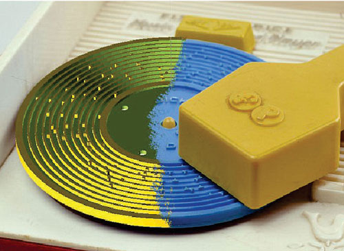
3D Printers Give New Life to Old Recordings

You know that 3D printers are being used to “produce” everything from parts of weapons to prosthetics, but have you heard of its usage in recordable technology?

The application of 3D printing in restoring old recordings is unheard of. But 3D printers are simply revolutionizing the industry of sounds.

nov13_c_RECORDINGIn this case, 3D printing technology has been applied to restoration. Researchers from the Lawrence Berkeley National Laboratory (LBL) have used 3D scanning technology to restore some century-old recordings made by three notable inventors that include Charles Sumner Tainter (inventor of an early telephone transmitter), Alexander Graham Bell, and his cousin Chichester Bell. These three inventors collaborated to bring about what was considered high-fidelity for audio systems (notably their graphophone) back in the 1880s. The team experimented using various mediums for their recordings that included discs and cylinders made from beeswax and cardboard, brass, and glass. Finally, they succeeded in making a series of recordings (more than 200 of them) on glass-based discs, which were sent to the Smithsonian in an effort to preserve them. However, they never sent the playback device needed to listen to the discs which were then considered useless and left to decay.

Decay they did – until the research team from LBL got hold of them. They brought them back to life through restoration and were able to play the recordings 125 years after they were made. To accomplish this, the team employed the use of a 3D scanner, known as IRENE, to non-invasively scan the discs and create a high-resolution image. They then processed the digital image, which pieces together the damaged disc and removes errors. The Lab used specialized software for calculating and recreating the engraving method (in this case, a stylus used to etch the glass/wax) to reproduce the audio into a digitized format. The team was successful at recovering the audio from six Volta Graphophone discs – it is looking to restore and preserve a host of early recordings from the Library of Congress. While giving new life to old technology, using 3D scanning is certainly impressive, 3D printing is capable of converting the latest technology in audio into a medium which very few still use.

Footwear – Changing styles through the decades

1910s: The First World War of 1914-1918 saw millions of men going to fight around the world. With women filling the jobs left vacant by the men’s absence, a desire for more practical women’s shoes for use in the factories was born. However, as shortages started to bite, the idea of being wasteful was severely criticized. With a lack of fabrics, dresses became shorter and the same design of lace-up boot that had been worn at the turn of the century was now viewed as practical rather than ‘old-fashioned’.

Suede became popular, and ballet-style pumps were decorated with a variety of removable buckles made from steel and decorated. Once peace was declared, fashions quickly changed in an effort to throw off the depression of wartime austerity.

1920s: This decade witnessed incredible changes in fashion in general – more liberal views on acceptable dress codes were forged. Dance crazes like the Charleston, which demanded a securely-fastened shoe with a low heel and a closed toe, influenced standard shoe design tremendously.

The discovery of ancient Egyptian Pharaoh Tutankhamen’s tomb in 1922 served to encourage a love of all things exotic, and this was reflected in shoe designs of the age. Brilliantly-dyed leather, metallic finishes and bright fabrics were used to create never-before seen designs, and rich brocades, satin, silk and velvet were often embellished with metallic overstitching, embroidery and fake gemstones. Heels were often decorated with crystals, often in Art Deco designs.

1930s: This was a decade that saw the world plunged into a financial depression after the US stock market crash of 1929. As in the First World War years, footwear needed to last longer and somber colours such as black, brown, maroon and navy blue became standard.

1940s: With the Second World War dominating everyone’s life for much of the decade, it was viewed as unpatriotic to be very fashionable during such a time of shortage. In much of the world, leather was reserved for military use, so shoemakers had to show initiative in their choice of raw materials. Reptile skins and mesh became popular alternatives.

1950s: After the war, optimism was high and stiletto heel, one of the great icons of fashion footwear, gained a massive following during the early part of the decade. Flat pumps based on the ballet shoe regained their popularity, and were quickly available in an incredibly diverse colour range.

1960s: Young people suddenly found themselves with more money to spend. This led to a decade of tremendous change, with highly experimental styles of fashion, music, art and literature. Hot pants and miniskirts took the Western youth market by storm, with flat-heeled high boots proving particularly popular. The hippie culture also became a major fashion and, as the race to be the first on the moon accelerated, new metallic ‘space-age’ materials (including coated plastic) were increasingly used by the world’s shoemakers.

1970s: Celebrities dressed to shock in the 1970s, with punk and glam rock encouraging dramatic styles that quickly found their way onto the high street. The birth of disco demanded comfortable dancing shoes, and strappy sandals became the choice of millions.

1980s: A new group of ambitious consumers with money to spend – well-paid young professionals nicknamed ‘Yuppies’ – looked to designer labels to emphasis their wealthy status in life, and retailers were only too pleased to supply just what they wanted. Many ‘new’ styles were actually updated versions of popular shoes from the 40s and 50s, with menswear influencing women’s fashions in the form of lace-up brogues.

1990s: While some glittering styles continued to hit the high street, the excesses of previous decades were replaced by more somber designs before the end of the millennium. A number of shoe fashion revivals took place, with 1970s-style chunky platform shoes regaining their popularity and pastel-colored ballet pumps once again proving to be a best buy.

2000s: Heels began to rise once more at the beginning of the 21st century, and the popularity of designer labels showed no signs of flagging. Embellishment of shoes with crystals, beads, embroidery   and exotic leathers arrived yet again – and has since proved to be a regular part of the footwear designer’s palette.

In the Middle East, heels were added to shoes to lift the foot from the burning sand.Pointed toes on shoes became symbol of wealth and power in Europe. They remained mostly in fashion between 11th and 15th century World’s biggest feet belong to Brahim Takioullah. . His shoe measures 40 cms in length (European shoe size: 58) and was produced at a cost of nearly 3000 Euros. At 8’1”, he is also the second tallest man alive.Penny Gold, a retired teacher, who lives in Florida, owns a staggering 733 pairs of converse sneakers. She has spent 15 years and $15,000 on her collection.

Most expensive shoes: Judy Garland’s ruby red slippers, used by her in the 1939 movie, “The wizard of oz”, remain the highest paid slippers ever auctioned – the winning bid was for $665,000.

Largest pair for shoes: One of the main attractions of Marikina, Philippines is the World’s Largest Pair of Shoes. It is located and displayed at the Riverbanks Center. The shoes measures 5.29 meters long, 2.37 meters wide and 1.83 meters high. The heel of the shoe was measured 41 centimeters or 16 inches. The shoes were made in the year of 2002. This was displayed for the First Sapatero Festival.

Courtesy: www.satra.co.uk

CAD/CAM in the footwear industry

In the footwear industry, Computer Aided Design and Computer Aided Manufacturing are used for designing and grading shoe upper patterns and, manufacturing of cutting dies, shoe lasts and sole moulds, respectively.

CAD was introduced in the shoe industry first in 1970s. Initially, it was used primarily for pattern grading. It enabled manufacturers to easily and quickly perform complex grading.

Today, CAD systems are used in a wide range of functions. Logos, textures and other decorations can be incorporated into product designs of both the uppers and soles to help reinforce branding on all areas of a model. CAD automates routine procedures, increasing speed and consistency whilst reducing the possibility of mistakes. CAD data can now be used effectively for a wide variety of activities across footwear manufacturing business. CAD/CAM generates data at the design stage, which can be used right through the planning and manufacturing stages.

Latest improvements in the CAD/CAM technology are:

  • Graphic capabilities and interconnectivity have improved enormously
  • Software developments have progressively made systems more intuitive and easier to use
  • With 2D sketch and paint modules, a serviceable sketch can be produced and then color and texture can be added
  • 3D systems enable the last and design to be viewed from any perspective and several angles even simultaneously.

With CAD/CAM software, footwear manufacturers can cut their time to market dramatically and hence, increase market share and profitability. In addition, the power and flexibility of the software can overcome restrictions to the designer’s creativity imposed by traditional methods.

Pattern grading

Shoe upper patterns need to be graded for the whole scale of the assortment of the required shoe sizes, which can be European, British or American sizing. Individual parts are graded instantaneously, which enables the designer to check the graded parts on the monitor. If any discrepancies are found, the designer can change the grading specifications immediately and re-grade the parts in no time.

Die making

Cutting dies made of steel are used in the shoe production to cut uppers from leather, textile or synthetics. Some CAD systems offer modules that enable long-distance transfer of data for shoe production preparation via modem or the Internet. The graphics data of patterns designed can then be transmitted easily to the die producer. The system also calculates the circumference of the die, which is the key factor of the die cost.

Automated leather

Automated cutting machines are widely used today in the footwear industry to cut uppers from leather, when die costs are relatively high for samples or low quantity styles. Computerized cutting systems use graphics data output of CAD systems as input.

Cost calculation

Using the graphics data generated, the CAD software can perform instant and highly accurate calculations for material consumption and product cost of the shoe, eliminating grueling and time-consuming work. It also helps in the introduction of detailed documentation and in effective staff training.

Shoe last design

Lasts can now be produced on a selection of numerically controlled lathes and milling machines using data output from CAD systems. Last shapes can be modified and new lasts created in the CAD systems. Variations in toe shape, heel curve and toe spring are easily achievable. Combining parts of different lasts also takes a few minutes with CAD technology.

It is possible to develop shoe design and tooling before the last physically exists because they are all derived from the same source data in the CAD system.

Easy modification of last shapes through CAD has enabled the development of software and procedures for orthopedic and customized footwear. Modules for materials and labor costing, lay planning and style specification sheets can be used early in the development of shoe styles.

Complex shapes can be generated, both rapidly and accurately, from the 3D computer representation of the appropriate last.

Sole design

CAD/CAM software can be used to generate machining data for shoe sole models and moulds. Shoe sole mould makers are able to strengthen their capabilities of mould design and production techniques to meet the market demands for shorter product life cycle, quality improvement and handling versatile pattern design. This helps especially sports shoe producers to manufacture products rapidly and to introduce them earlier than their competitors.

3D CAD/CAM is the core technology for shoe sole mould in the footwear industry and develops towards specialization.

Benefits of CAD/CAM in the mould manufacturing are:

  • Total modeling for rapid generation of design concepts and variations
  • Reverse engineering from existing models or parts
  • Easy design modification and morphing capability
  • Completely accurate designs regardless of complexity
  • Group grading of soles and uppers
  • Advanced decorating techniques
  • Realistic onscreen visualization
  • Rapid generation of molds from product designs

The Geometric Design of Roads and Highways – An overview

The geometric design of roads is a branch of highway engineering. It is concerned with the positioning of the physical elements of a roadway, according to standards and constraints.

The basic objectives of geometric design are to optimize efficiency and safety of roadways, while minimizing cost and environmental damage. In addition, there is an emerging objective of “livability”, which is about designing roads to foster broader community goals such as providing access to employment, schools, businesses and residences, and accommodate a range of travel modes such as walking, bicycling, transit, and automobiles, and minimizing fuel use, emissions and environmental damage.

Geometric roadway design can be broken into three main parts:

The alignment is the route of the road, defined as a series of horizontal tangents and curves.

The profile is the vertical aspect of the road, including crest and sag curves, and the straight grade lines connecting them.

The cross section shows the position and number of vehicle and bicycle lanes and sidewalks, along with their cross slope or banking. Cross sections also show drainage features, pavement structure and other items outside the category of geometric design.

Basic design controls serve as the foundation for establishing the physical form, safety, and. functionality of the transportation facility. Some design controls are inherent characteristics of the facility (e.g., its physical context and the existing transportation demands, placed upon it).

Other basic design controls are selected or determined by the designer, working with communities and users to address a project’s purpose and need. Road having following element and their influence on the physical characteristics of a roadway or other transportation facility are:

Roadway Context: The context of a roadway is a critical factor to consider in developing a project’s purpose and need in making fundamental design decisions such as cross-section determination, and selecting detailed design elements such as street light fixtures or other construction materials. Development of a roadway design that is sensitive to, and respectful of the surrounding context, is important for project success.

Roadway Users: A fundamental expectation in roadway design is that all users will be accommodated safely. Early in the process, the designer needs to determine the composition of users anticipated for the facility.

The Cyclist: Safe, convenient and well-designed facilities are essential to encourage use of bicycle. Roads designed to accommodate cyclists with moderate skills will meet the needs of most riders.

Transportation Demand

Transportation demands – volume, composition, and patterns – are important design controls. The greater the demand for a facility, the more important are its operation and safety characteristics.

Design Year: Projects are designed to accommodate travel demands likely to occur within the life of the facility under reasonable maintenance. This involves projecting future conditions for a selected planning horizon year.

Volume and Composition of Demand: The composition of transportation demand is an important element in the design of roadways. The designer should develop a realistic design scenario including the volume and mix of activity for all modes as described below.

Pedestrian Demands: Pedestrian counts should be completed to determine pedestrian flows and patterns. The pedestrian counts should include sidewalk demands, crossing demands, and storage demands at corners, traffic islands, and median (total number of pedestrians waiting to cross the street).

Bicycle Demands: Bicycle demands should be counted during peak hour’s concurrent with vehicle turning movement counts. As the pedestrian activity, the designer should also evaluate the project area to determine if there is potential latent demand for bicycles accommodation.

Motor Vehicle Traffic Volumes: Daily, peak hour, and patterns of motor vehicle traffic are needed as input to the planning and design of roadway facilities. Some key definitions of traffic volume measures are listed here:

  • Average Annual Daily Traffic (AADT): The total yearly volume of automobiles and trucks divided by the number of days in a year.
  • Average Daily Traffic (ADT): The calculation of average traffic volumes in a time period greater than one day and less than one year.
  • Peak-Hour Traffic (PH): The highest number of vehicles passing over a section of highway during 60 consecutive minutes.
  • Peak-Hour Factor (PHF): A ratio of the total volume occurring during the peak hour to the maximum rate of flow during a given time period within the peak hour (typically is 15 minutes).
  • Design Hourly Volume (DHV): The one-hour volume in the design year selected for determining the highway design.

Measure of Effectiveness

Through the project development process and with public input, the designer should evaluate the project using several measures evaluate the project using several measures discuss transportation or contextual of effectiveness.

National or state transportation policy places an emphasis on improving the condition of existing facilities. Projects on existing facilities should return a facility to state of good repair by addressing existing structural, pavement surface, or other deficiencies.

The safety of transportation facilities is a primary concern in planning and design. Some projects are specifically proposed to address known safety problems; however, all projects should result in a facility that safely accommodates its users.

Many projects result in improved accommodation for particular modes. The effectiveness of these projects can be measured by the degree to which they allow users to choose the mode best-suited to their trip purpose and personal values within the broader framework of the community, the region and the environment.

Slight Distance

Sight distance is the length of roadway ahead that is visible to the roadway user. In most cases, specific sight distance measures apply to motor vehicles and cyclists. The following aspects are commonly discussed for motor vehicle sight distance:

Motor Vehicle Stopping Sight Distance: Stopping sight distance is the distance necessary for a vehicle travelling at the design speed to stop before reaching a stationary object in its path. The sight distance at every point along a roadway should be at least the stopping sight distance.

Passing Sight Distance: For two-lane highways, passing manoeuvers in which faster vehicles move ahead of slower vehicle must be accomplished on lanes regularly used by opposing traffic. If passing is to be accomplished safely, passing sight distance is necessary to allow the passing driver to see a sufficient distance ahead.

Decision Sight Distance: Decision sight distance adds a dimension of time to stopping sight distance to allow a driver to detect and react to an unexpected condition along a roadway. Decision sight distance is suggested when there is evidence that it would be prudent to provide longer sight distance, such as when complex decisions are needed or when information is difficult to perceive.

Speed

Speed is an important factor considered by travellers in selecting a transportation mode or route. Speed can also influence the physical characteristics of the transportation infrastructure. Many design elements such as horizontal and vertical curvature and super elevation are directly related to speed. The objective in the planning and design of a roadway is to determine a speed that is appropriate for the context results in a safe facility for all users, is consistent with the community’s goals and objectives for the facility, and meets user’s expectations. Once an appropriate speed is selected, the designer needs to tailor design elements to that speed.

Conclusion

In geometric design of roads and highways, the basic design controls serve as the foundation for establishing the physical form, safety, and functionality of the transportation facility. Some design controls are inherent characteristics of the facility. Other basic design controls are selected or determined by the designer, working with communities and users to address a project’s purpose and need. Selecting appropriate values or characteristics for these basic design controls is essential to achieve, safe, efficient, cost effect, sustainable and context sensitive design.

Courtesy: www.en.wikipedia.org | www.nbmcw.com

Bentley MXROAD

Bentley MXROAD is an advanced, string-based modeling tool that enables the rapid and accurate design of all road types. With MXROAD, you can quickly create design alternatives to build the ideal road system. After a final design alternative is selected, you can automate much of the design detailing process, saving time and money.

MXROAD uses 3D string modeling technology-a powerful yet concise method of creating 3D surfaces. The interoperable database allows engineers to create and annotate 3D project models in the most popular AEC platforms or in Windows. This means that you can work on the project within one environment, save it, and open it seamlessly in another environment with no loss of data. This promotes maximum productivity of trained staff. CADD Centre’s 64 hour course on MXROAD is designed to provide a solid foundation in the use of the interactive functions in MXROAD. This will enable engineers or technicians to operate the system confidently through a good understanding of the principles of surface modeling and the design functions of MXROAD.
Changes in the PMBOK 5th Edition – An important note for PMP Credential holders and PMP Aspirants:

What is New in the PMBOK 5th Edition?

The fifth edition of A Guide to the Project Management Body of Knowledge: (PMBOK® Guide) was published in December of 2012. It is the latest edition of the global project management standard published by the Project Management Institute (PMI)®. The release of this new edition has consequences for anyone who is preparing for the Project Management Professional (PMP) ® exam.

In the 4th Edition of the PMBOK Guide there were 5 process groups and 42 processes. And in the 5th Edition, the number of process groups is same but the processes have been increased to 47.

The major change in this new edition of the PMBOK Guide is an addition of a new Knowledge Area –“Project Stakeholder Management”. In the fourth edition of the PMBOK Guide, this was a part of the Communication Management knowledge area. This new knowledge area has four processes in it.

This change shows that PMI gives importance to stakeholder management and it is very imperative for you to manage them if you want to complete your project successfully.

Five additional processes are as follows:

Four planning processes are added to different knowledge areas (plan scope management, plan schedule management, plan cost management, and plan stakeholder management). These four planning processes bring a consistency to the Project Management knowledge areas. Now, the knowledge areas (that make the Project Management plan) start with a concerned subsidiary plan.

Two communication processes are merged into one process (Distribute Information and Report Performance to Manage Communications).

Two new controlling processes are added (Control Communications and Control Stakeholder Management).

Two processes are relocated to the Stakeholder Management knowledge area.

Some additional changes are as follows:

Verify Scope is changed to Validate Scope.

Administer Procurement is changed to Control Procurement.

Direct and Manage Project Execution is changed to Direct and Manage Project Work.