MEP Engineering:

What Brings Buildings and Structures to Life

apr_14_aaCivil engineering is considered one of the oldest engineering disciplines, encompasses many specialties. The major specialties are structural, water resources, construction, environmental, transportation, and geotechnical engineering. However, MEP engineering has also emerged as a specialty in the building design field.

Also known as building services engineering, MEP Engineering involves mechanical, electrical and plumbing services of a construction project. MEP engineering, essentially, focuses on the internal environment and environmental impact of a building. It essentially brings buildings and structures to life.

The mechanical engineering activities, taken out as part of MEP engineering, are broadly about design of heating, ventilation and air conditioning (HVAC), plumbing, and rain gutter systems. The electrical engineering would involve designing a building’s power distribution, telecommunication, fire alarm, signalization, lightning protection and control systems, as well as lighting systems. And the plumbing part is concerned with the designing of systems of pipes, tanks, fittings, and other apparatus required for the water supply, heating, and sanitation in a building. Plumbing design often includes design specifications for simple active fire protection systems, but for more complicated projects, fire protection engineers are often separately retained.

One who knows about Mechanical, Electrical and Plumbing (MEP) works in the construction industry can be qualified as a MEP Engineer. Usually a Electrical or Mechanical Engineer can manage MEP assignments.

Some of the widely known MEP services include:

  • Energy supply – gas, electricity and renewable sources
  • Heating and ventilating
  • Water, drainage and plumbing
  • Fire detection
  • Lighting design
  • Ventilation and refrigeration
  • Harnessing solar, wind and biomass energy
  • Air conditioning and refrigeration
  • Power distribution
  • Electricity generating plant
  • Lightning protection
  • Controls/building management systems

MEP engineers also provide services including site investigations, value engineering, feasibility studies, indoor environmental analysis, system analysis and troubleshooting, building controls automation, due diligence reports, construction phase services, operation & maintenance consulting, and green & energy consulting.

MEP engineers have to be good at MEP software products in order to create MEP drafting, MEP design, MEP drawings and MEP detailing. MEP design is critical for design decision-making, accurate documentation, performance and cost-estimating, construction planning, managing and operating the resulting facility.

MEP engineers use specialized CAD software programs to assist in their system design and analysis. CAD for MEP engineering offers many benefits, including easier and more exhaustive visualization of proposed solutions, the ability to create virtual models for analysis and calculations, and the ease of use in spatial planning.


Revit MEP software:

An Overview

apr_14_bAutodesk Revit is Building information modeling (BIM) software for architects, structural engineers, MEP engineers, designers and contractors. It allows users to design a building and structure and its components in 3D, annotate the model with 2D drafting elements and access building information from the building models database. Revit is 4D BIM capable with tools to plan and track various stages in the building’s lifecycle, from concept to construction and later demolition. The latest released version is Revit Architecture / Structure / MEP 2014.

Revit is specifically built for Building Information Modeling (BIM) and has comprehensive features that make it an idea solution for the entire building team. You can use Revit to design, build, and maintain higher-quality, more energy-efficient buildings.

Revit MEP is the design and construction documentation solution for mechanical, electrical, and plumbing (MEP) engineering. Revit MEP allows engineers to see their designs before they’re built, allowing them to accurately create MEP systems for today’s complex architectural designs. All changes are automatically coordinated everywhere in a project.

It lets engineers to seamlessly collaborate

with architects using Revit Architecture software in an intuitive design environment. Engineers can minimize coordination errors with architects and structural engineers using the Revit platform and building information modeling (BIM) workflows. They can provide better decision making and building performance analysis support for the engineer.

Revit supports more accurate and efficient building systems design projects from concept through construction. Engineers can design building systems more accurately using coordinated, consistent information inherent in the intelligent Revit MEP model and analyse for efficiency with integrated analysis earlier in the process.


Engineers can keep documentation coordinated and consistent with parametric change management technology and deliver 3D models and documentation to support the building lifecycle.

Following are some of the key features of Revit MEP and their applications:

Point Cloud support – to capture existing conditions and visualize point clouds.

Model building systems – to use mechanical, electrical and plumbing design tools.

System design tool enhancements – to add details to ducts and pipes such as insulation and lining, and use sloped piping tools.

Modeling enhancements – to create duct and pipe placeholders and later convert to detailed objects. Add parallel pipe and conduit runs.

Panel Schedules – to display panel schedule totals in current or load values.

Construction documents – to automatically generate plans, sections, elevations and details.

Revit Server – to maintain integrated Revit models on a single server, and access from local servers.

Other key highlights of Revit MEP are: It supports sustainable designs by performing building performance analysis using integrated tools as well as partner applications.

And with parametric change technology, any change that engineers make is automatically coordinated everywhere in their project including model views, drawing sheets, schedules, sections, and plans.

Designed for an intuitive, straightforward design process, Revit MEP mirrors the real world of engineering. It works holistically, treating information in terms of the entire building, linking mechanical, electrical, and plumbing systems with the building model.

Engineers can get design feedback instantly from the building information model when working within a Revit based architectural and engineering (A&E) workflow, and realize the benefit of data-driven design to easily keep track of a project’s scope, schedule, and budget.

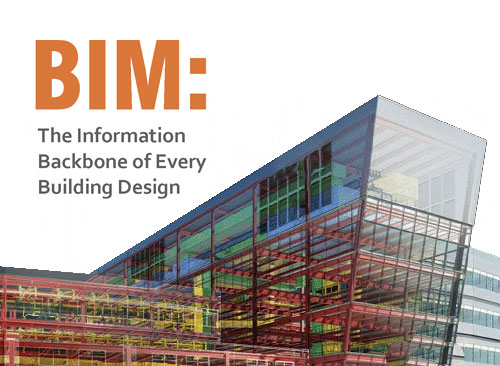
BIM: The Information Backbone of Every Building Design

apr_14_aBuilding Information Modeling (BIM) is a process involving the generation and management of digital representations of physical and functional characteristics of places. BIMs are files (often but not always) that can be exchanged or networked to support decision-making about a place.

Current BIM software is used by individuals, businesses and government agencies who plan, design, construct, operate and maintain diverse physical infrastructures, from water, wastewater, electricity, gas, refuse and communication utilities to roads, bridges and ports, from houses, apartments, schools and shops to offices, factories, warehouses and prisons, etc.

The concept of BIM has existed since the 1970s. However, the term “Building Information Model” first appeared in an article in 1992. However, it was not popular until Autodesk released a white paper titled “Building Information Modeling”.

 The Definition

According to the National Building Information Model Standard Project Committee, BIM can be defined as: “a digital representation of physical and functional characteristics of a facility. A BIM is a shared knowledge resource for information about a facility forming a reliable basis for decisions during its life-cycle; defined as existing from earliest conception to demolition.”

Traditional building design was largely reliant upon two-dimensional drawings (plans, elevations, sections, etc.). Building information modeling extends this beyond 3D, augmenting the three primary spatial dimensions (width, height and depth) with time as the fourth dimension (4D) and cost as the fifth (5D), etc. BIM therefore covers more than just geometry. It also covers spatial relationships, light analysis, geographic information, and quantities and properties of building components (for example, manufacturers’ details).

BIM involves representing a design as combinations of “objects” – vague and undefined, generic or product-specific, solid shapes or void-space oriented (like the shape of a room), that carry their geometry, relations and attributes.

For the professionals involved in a project, BIM enables a virtual information model to be handed from the design team (architects, surveyors, civil, structural and building services engineers, etc.) to the main contractor and subcontractors and then on to the owner/operator; each professional adds discipline-specific data to the single shared model.

This reduces information losses that traditionally occurred when a new team takes ‘ownership’ of the project, and provides more extensive information to owners of complex structures.

Future Outlook

BIM is a relatively new technology in an industry typically slow to adopt change. Yet many early adopters are confident that BIM will grow to play an even more crucial role in building documentation.

Proponents claim that BIM offers:

Improved visualization

Improved productivity due to easy retrieval of information

Increased coordination of construction documents

Embedding and linking of vital information such as vendors for specific materials, location of details and quantities required for estimation and tendering

Increased speed of delivery

Reduced costs

BIM also contains most of the data needed for building energy performance analysis. The building properties in BIM can be used to automatically create the input file for building energy simulation and save a significant amount of time and effort. Moreover, automation of this process reduce errors and mismatches in the building energy simulation process. Hence, one can be rest assured that BIM is well on its way to become a mainstream idea in engineering. CADD Centre’s National Design Competition 2014 Attracts Participation of 25,000 Engineering Students

CADD Centre’s National Design Competition 2014, attracted the participation of about 25,000 engineering and polytechnic students across the country. The month-long event, involving four different rounds, was kick-started on February 2, 2014 and culminated with a grand final on March 3, 2014. The competition was meant for second, third and final year students of engineering colleges and polytechnics. Exclusive themes were given for students representing various engineering streams. The winners of civil & architecture stream (Building Design) were: Mr Aditya Singh Parihar of Indore, and the winner of the mechanical stream (Product Design) was Mr. Dhananjay Premraj Patil of Mumbai.

The winners were presented with the Best Designer Award and a cash prize of Rs 1lakh each. The runners-up of the competition were: Mr. R. Biju of Marthandam (Building Design) and Mr. Devesh Jangir of Jaipur (Product Design). The runners-up received a trophy and certificates, along with the cash award of Rs 30,000 each. All the participants of the final round were awarded a Consolation Certificate and cash prize of Rs 10,000.

Truss Me! App

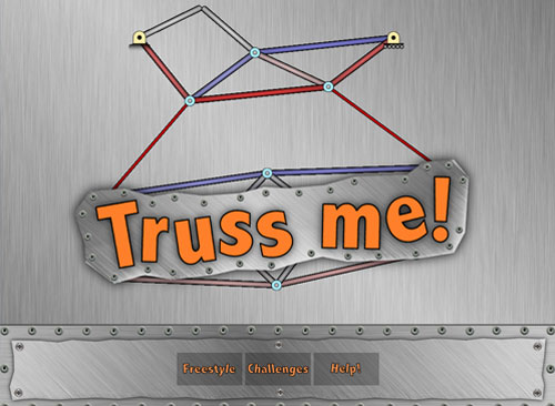
mar_14_appAs gaming has entered the realms of education, a new “app” was designed to teach structural engineering, called Truss Me! is creating waves online. In engineering, a truss is a structure comprising five or more triangular units constructed with straight members whose ends are connected at joints referred to as nodes. Truss is derived from Old French trousse, around c.1200, which means “collection of things bound together. A truss structure is composed of bars connected through joints. Joints are very important for truss structures, as they carry all weights (loads) and provide the connection points to the ground (constraints).

The success of the Truss Me! app may be explained by the fact that it feels and looks like a game, even though the simulation engine running behind the scenes is truly state-of-the-art. The app, including its algorithms, was designed by a US professor.

The app is developed to help students acquire some intuition as to how truss structures behave through state of the art simulations.

The game has two playing modes. In the freestyle mode, students are encouraged to design and test their own structures. In the challenges mode, students have to solve structural puzzles in order of increasing level of complexity.

The developer of the game used trusses as the fundamental component of the game for several reasons. Firstly, trusses are everywhere. Students can see them everywhere in their daily life. They are in bridges, roofs, cranes, stadiums, power lines and more.

Trusses are also simple. “All you need to understand the behaviour of a truss is the notion of tension and compression. Consequently, there is no need to explain complicated concepts such as shear and bending. Yet, despite their simplicity, trusses allow you to explain all the main concepts of structural mechanics: loads are related to deformations, deformations are related to stresses, and stresses are related to failure,” the professor says.

Truss Me! utilizes state of the art simulation techniques used by aerospace, mechanical, and civil engineers to provide the most realistic behavior for your structures. It is available for purchase on the App Store.

Cadd Centre Annual Meet At Chennai

Changes in the PMBOK 5th Edition

– An important note for PMP Credential holders and

PMP Aspirants:

What is New in the PMBOK 5th Edition?

dec13_cmEETThe fifth edition of A Guide to the Project Management Body of Knowledge: (PMBOK® Guide) was published in December of 2012. It is the latest edition of the global project management standard published by the Project Management Institute (PMI)®. The release of this new edition has consequences for anyone who is preparing for the Project Management Professional (PMP) ® exam.

In the 4th Edition of the PMBOK Guide there were 5 process groups and 42 processes. And in the 5th Edition, the number of process groups is same but the processes have been increased to 47.

The major change in this new edition of the PMBOK Guide is an addition of a new Knowledge Area –“Project Stakeholder Management”. In the fourth edition of the PMBOK Guide, this was a part of the Communication Management knowledge area. This new knowledge area has four processes in it.

This change shows that PMI gives importance to stakeholder management and it is very imperative for you to manage them if you want to complete your project successfully.

Five additional processes are as follows

Four planning processes are added to different knowledge areas (plan scope management, plan schedule management, plan cost management, and plan stakeholder management). These four planning processes bring a consistency to the Project Management knowledge areas. Now, the knowledge areas (that make the Project Management plan) start with a concerned subsidiary plan.

Two communication processes are merged into one process (Distribute Information and Report Performance to Manage Communications).

Two new controlling processes are added (Control Communications and Control Stakeholder Management).

Two processes are relocated to the Stakeholder Management knowledge area.

Some additional changes are as follows:

Verify Scope is changed to Validate Scope.

Administer Procurement is changed to Control Procurement.

Direct and Manage Project Execution is changed to Direct and Manage Project Work

AVEVA PDMS.

PDMS includes comprehensive functions for all aspects of 3D plant design.

 Features:

A fully interactive, intuitive 3D plant design environment, with a Microsoft Office-style user interface based on .NET technologyHundreds of designers can work concurrently on a project, in a fully controlled manner, with visibility of the entire design at all times.Designers progressively create a highly intelligent 3D design by selecting and positioning parametric components from an extensive catalogue.Clash checking and configurable integrity checking rules help a designer create ‘right first time’ design and enable effective overall design quality assurance.  A configurable Status Management function provides visual highlighting and clear reporting of design maturity status of PDMS objects. Highly configurable, automatic generation of a wide range of reports and drawings direct from the PDMS database Information Sharing

Share catalogue information across multiple projects, for consistency and standards compliance Share information between AVEVA Plant™ applications for Integrated Engineering & Design Use with AVEVA Global for seamless multi-site collaboration on a single, common project model Citrix Ready, for operation in a Cloud environment.

Catalogues & Specifications An extensive set of catalogues covers industry, national, and international standards, and includes piping, structural steel, ducting, hangers, supports and cable trays.

Each catalogue provides parametric definition of all components in the required size ranges, ratings and types. For piping components, for example, data is stored related to connection types, physical and nominal size, material codes and bolt requirements. Engineering specifications control the way in which catalogue components may be used in the design.Standard catalogues can be defined once and shared across multiple projects. Controlled changes to components and specifications are quick and easy to make and apply across the design.