SOLIDWORKS 2018 Debuts

SOLIDWORKS is back again in the year 2018. The package has some added tools, enhancements and features to give you a completely new experience. Right from the welcome screen, the application has new and improved data management capabilities, integrating CAM feature along with some other innovative functionalities making it again your best design partner.

Pen and Touch-Enabled Devices: The application supports new touch-enabled capabilities. This is one of the most significant changes that came with SOLIDWORKS 2018. Now, you can make sketches using a touch-enabled pen. The application even supports customized mouse gestures making it more user-friendly and interesting to use.

Adding Granular Details: SOLIDWORKS 2018 has come up with new capabilities to work with assemblies such as Adding Mates Between Hidden Surfaces, Misaligned Mates, and Smart Explode Line Tool. The application has also introduced a new Tab and Slot feature for the sheet metal design. Now you can create the inspection documentation directly from 3D models.

CAM Integration: The most promising feature that SOLIDWORKS 2018 brought about is the CAM integration. The feature is called SOLIDWORKS CAM and works as a new application. The capability leverages CAM technology which is pretty interesting software in itself. Such integration will automate the entire manufacturing programming.

Enhancing the Complete Cycle: SOLIDWORKS 2018 comes with an integrated approach that works with your product right from design to manufacturing. This is done by putting the part or the assembly model in the Centre of the action. The concurrent collaboration capabilities of SOLIDWORKS 2018 keeps the data well managed so that you can create a design using manufacturing strategy across the product development workflow.

Ease in CNC Programming: The application has come up with new part and assembly machining, a 2.5 axis milling, and two-axis turning features. Such a feature is capable to make CNC (computer numerical control) programming less time consuming and simple.

Automating the Manual Inspection Process: The revised version of SOLIDWORKS has automated inspection capabilities. This feature helps you to save time skipping the manual inspection process. Dassault now claims that the 2018 version can carry out the article inspection process and generate reports in minutes.

Dealing with the corrupted files: If your repair attempts fail to resolve a corrupted file, SOLIDWORKS 2018 now prompts you to extract your geometrical details if data about the body is still intact. You can use this extracted data to create a new model.

Skill Development and Career Future in CAD Industry

The world has experienced a huge rise in Information and Technology in the recent past years. The current scenario in the field of science and technology have showcased the power of technology and skills. Being one of the fastest growing economies in the world, India needs a more skilled workforce to compete with the world.

A Degree isn’t Enough 

When it comes to technical graduates, there is a countless number of engineers that pass out every year. But these graduates still lack the skills and expertise required by the industry. Engineering graduates undoubtedly have good grades. Still, there is huge talent gap that needs to be filled to make them immediately employable.

Graduates Needs to be Multiple Taskers 

Employers across the industries are always hunting for people that are multiple taskers. This means that graduates need to have more than one skill or even one particular mastered skill. Not only technical skills, but the industry also expects the graduates to have a personality and soft skills to work in the industry.

Need of Skill Development 

With the change in technology, the industry today needs more skilled manpower. For instance, regarding CAD, all the manual work is replaced by computers and drawing pencils are replaced by mouse. Thus, to fulfill the needs of the employers and to make a future in the industry, the youth needs some additional technical training.

Career in CAD Industry 

CAD technology is most widely used technology across industries. Civil, Electrical and Mechanical domains are hiring technical graduates that are well acquainted in CAD and its applications. It is therefore, important for the engineers to learn and master these skills. CAD is one of the lucrative fields in the market that demands highly skilled and compete engineers for the market.

India expects highly skilled man force from the upcoming generation. These expectations can only be met when the engineers are technically trained to work across the industries.

Four Key Advanced Manufacturing Technologies Used in Aerospace

Advanced Manufacturing technologies have become one of the most important parts of the Aerospace industry. This is because of the unique challenges that the aircraft designers deal with. The aircraft designs need to consider the environmental conditions using strong materials that are both lightweight and temperature resistant. Such designs require micro and Nano- machining techniques. Here are four advanced machining technologies that are used in the Aerospace industry.

Additive Manufacturing  

The Aerospace industry was quick to identify the benefits and potential of Additive Manufacturing to design its planes. The technology uses Power-Bed laser printing systems to build its most components. Additive manufacturing technology is used to build structures that work within the fuselage with features such as reduced weight and reduce heat. An additive manufacturing technique, commonly known as the Fused Deposition Modeling, is used to create semi-hollow parts of the aircraft wings by both adding strength and reducing weight.

Composite Materials

Composite materials are widely used to design aircraft. Aerospace engineers prefer using these materials because of their favorable characteristics of flexibility, strength, temperature and chemical resistance. Composite materials and advanced polymers in the design help to improve performance and reduce lifecycle costs. These materials also reduce the overall weight of the aircraft cutting short their fuel consumption and carbon emissions.

Robotics

Robots are used in the aerospace industry to manage the labor-intensive process, particularly when lifting and handling tasks are to be done. The industry is using powerful robots in its manufacturing plants to move and join aircraft parts. Robotics is also taking care of manufacturing process that is hazardous to people such as painting and welding.

Laser Beam Welding

This technology offers rapid and high precision work as compared to the traditional welding techniques. Laser welding is, therefore, a preferred solution for handling materials when repeatability and high accuracy is required. The most advantageous property of this technique is that it transfers very little heat to the material that is welded. This way it does not create a heat affected zone around the weld, ultimately not compromising the strength and performance of the material.

With the widespread use of these technologies, the aerospace industry has also inspired several other industries to use these technologies in the manufacturing process. These techniques have undoubtedly simplified the manufacturing processes and reduced costs to a greater extent. Their accuracy and precision have reduced the number of failure points in the manufacturing process.

ARES Commander 2017 – An Overview

Graebert has recently released a new version of its flagship CAD product:             ARES Commander 2017. The product offers 2D and 3D tools for CAD designing in DWG format. Graebert’s  30+ years of expertise in CAD for computers and mobile devices makes this new software all the more unique and trustworthy.

Product Specification

Below listed are the unique features of ARES Commander Software 2017.

  • Platform independent: The software is compatible with Windows, Mac OS, and Linux platforms.
  • DWG Native: The software uses DWG as its native format, allowing modification of CAD designs in this popular format, without explicit import and export.
  • User-Friendly Interface: The software has an interface similar to the generic CAD interface and implements the similar CAD operating commands for ease of use.
  • Resolves Language Barriers: Available in 14 different languages: English, French, Spanish, Italian, German, Polish, Czech, Russian, Turkish, Brazilian Portuguese, Japanese, Simplified Chinese, Traditional Chinese, and Korean.
  • Programming Interface: Incorporates powerful API, which supports numerous programming languages including C++, TX, Lisp, VSTA, DCL, Visual Studio, COM, and Active X.
  • ARES Touch: The best touch screen solution for CAD on smartphones and tablets is now available for both Android and iOS. Further, the Dark user interface is the part of this new software.

Software Application

The new features incorporated in this version makes the software robust. These additional features are as follows.

  • Multifunctional Grips helps the user to modify any entity using end point grips. One can easily alter the length, width, and radius of any entity using this functionality.
  • Polylines editing improvements permit the user to convert a line segment into an arc and vice versa.
  • Relative angles in coordinate input can be easily entered using “@” prefix.
  • The software helps to Trim and Power Trim the hatches and gradients.
  • Advanced PDF to DWG conversion
  • Insert CENTERLINES between a pair of lines, concentric arcs and polyline segments.
  • The software helps to create an array of multiple copies of a selected entity along any path.
  • Splits dimension lines and extension lines avert overlapping.
  • Xtra tools are LISP based tools which are now available for the MAC and Linux OS as well. It includes tools for annotations, modifying blocks and dimensions, and views and utilities.
  • One can easily match the entity properties with the layer’s properties using SetByLayer option of the software.

The latest version of ARES Commander Software will help the users to create compelling DWG drawings. The simple interface and advanced features will make CAD implementation easy and organized.

Simulating Is Believing

The Simulation tools are making it easier for manufacturers to optimize the process, visualize the entire production path from metal cutting simulations and factory-floor imaging. With the latest tools, the toolpath designers and manufacturing engineers will be able to fix things, speeding the simulation and verification of metal cutting process.

Manufacturers are focusing on ongoing trends for spreading the wealth with higher-end simulation tools throughout the design/production chain.

Sharing CAE with the Masses

From all the latest simulation trends, wider adoption of CAE tools such as topology optimizations, finite element analysis has begun to make way towards manufacturing operations, as engineers outside CAE leverage the power of these simulation technologies. The simulation techniques are applied all across the manufacturing process such as assembly simulation, robotics simulations, human simulations, and ergonomics. Correspondingly, the process of simulation helps in earlier detection of a potential problem, which directly leads to faster processing, increasing tool life, and reduced material cost. Though, the democratization of CAE tools can be experienced for structural analysis, composites manufacturing, and others but, is yet to reach its full potential.

Optimized Drilling

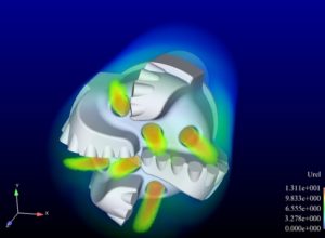
Machine expensive corrosion-resistant materials are difficult on drills, to which researchers used fluid flow and structural analysis tools to analyze the coolest fluid distribution and achieve longer tool life. Right from the inclusion of methods to extend the life of drills for the use, a significant amount of heat transported or directing the coolant fluid into small channels. To understand the complex interaction of drill structure, the research team included simulation tools for process optimization by performing fluid-structure interaction analysis. The entire process involved the use of computational fluid dynamics (CFD) and mechanical simulations to modify the cooling process and to improve the tool life by about 50%.

Validating the Digital Factory Drilling

New digital manufacturing simulation tool such as FastSuite Edition 2 enables significant operations, amongst which a few are listed, hereby:

  • It helps manufacturers to design factory layout and optimizing product designs.
  • It validates manufacturing processes in advance and fastening of the same process and optimizing designs.
  • FastSuite also provides user-friendly functions for integrating new and project-specific components in the layout.
  • It uses shared memory to write the simulation data and from which 3D visualization then reads the simulation data.

Therefore, the 3D based simulation software allows validation and visualization of processes and production tasks.

In the end, the involvement of simulation tools can handle customized markets, making of adjustable product structure, and complexity of big orders.